 F. L. I. G.
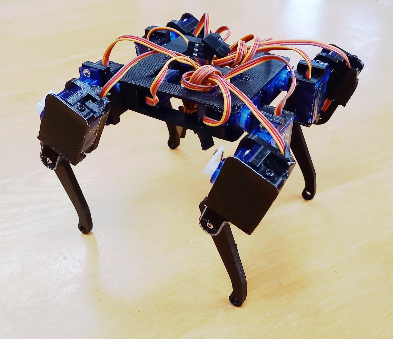
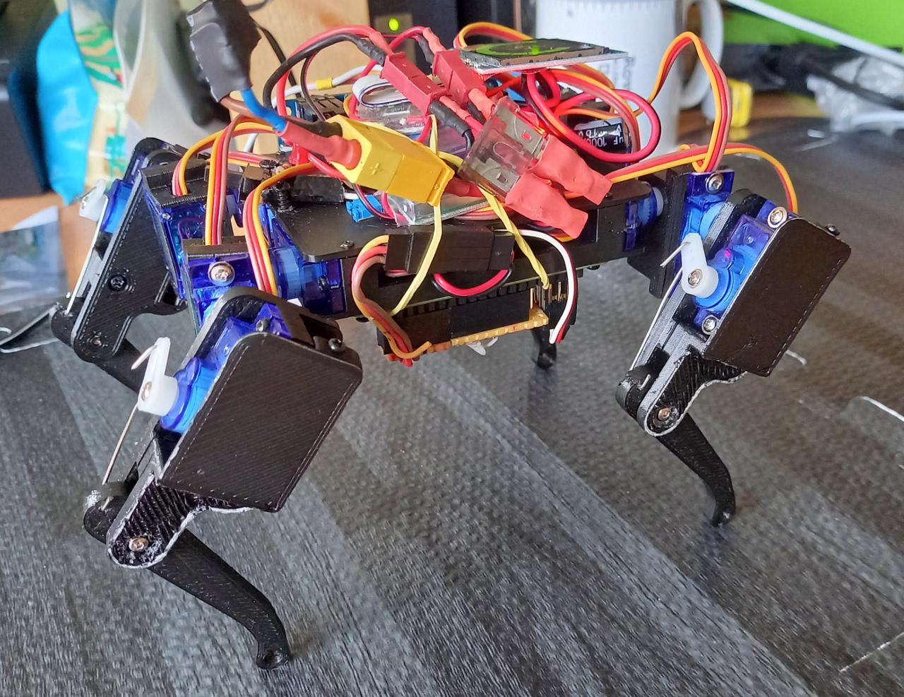
With one leg done, it is relatively easy replicating it 4 times and adding square frame to put shoulder servos inside.
But that's just shell without any guts. Breakout boards PCA9685 for 16 servos is the perfect for the job along with PiZero2W. Also, if servos are properly grouped we can utilise INA3221 - a three channel, 13bit, i2c current/voltage monitor. As it is very easy to set up i2c address of INA3221 - we can use two or even three to monitor voltages and currents through our robot.
Two INA3221 breakout boards are going to give us 6 channels in total, so servos can be grouped like this:
- each leg's shin and thigh servos together on one channel (four channels)
- two shoulder servos on one side on another and
- two shoulder servos on the other side on last channel
To achieve this there were some cutting of the lines on the breakout board:
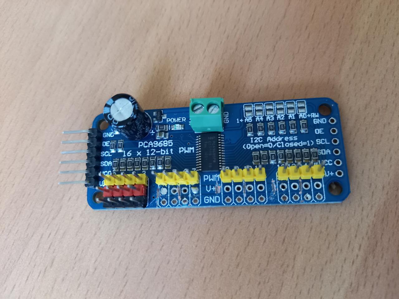
Last 12 servo outputs are cut VCC line (two by two) and two INA3221 are connected to PCA9685's VCC and each channel to pair of servo VCCs. First four servos are driven without any current monitoring.
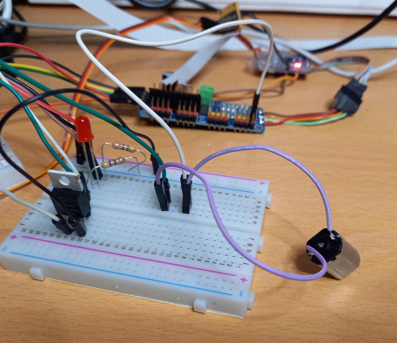 Also, some servos cannot be 'stopped driven' by just stopping sending servo signals, some servos like digital servos.
Analogue servos, when they 'lose' signal just go limp, but digital servos do 'remember' what was the last signal like and
keep holding servos. So, to overcome it we need slightly strong MOSFET to directly drive our servos - controlled by simple GPIO line.
Also, some servos cannot be 'stopped driven' by just stopping sending servo signals, some servos like digital servos.
Analogue servos, when they 'lose' signal just go limp, but digital servos do 'remember' what was the last signal like and
keep holding servos. So, to overcome it we need slightly strong MOSFET to directly drive our servos - controlled by simple GPIO line.
Aside of measuring voltage and current for (leg) servos, we can measure voltage and current on electronics as well - through INA219. It is very similar in specs as INA3221 but it has only one channel.
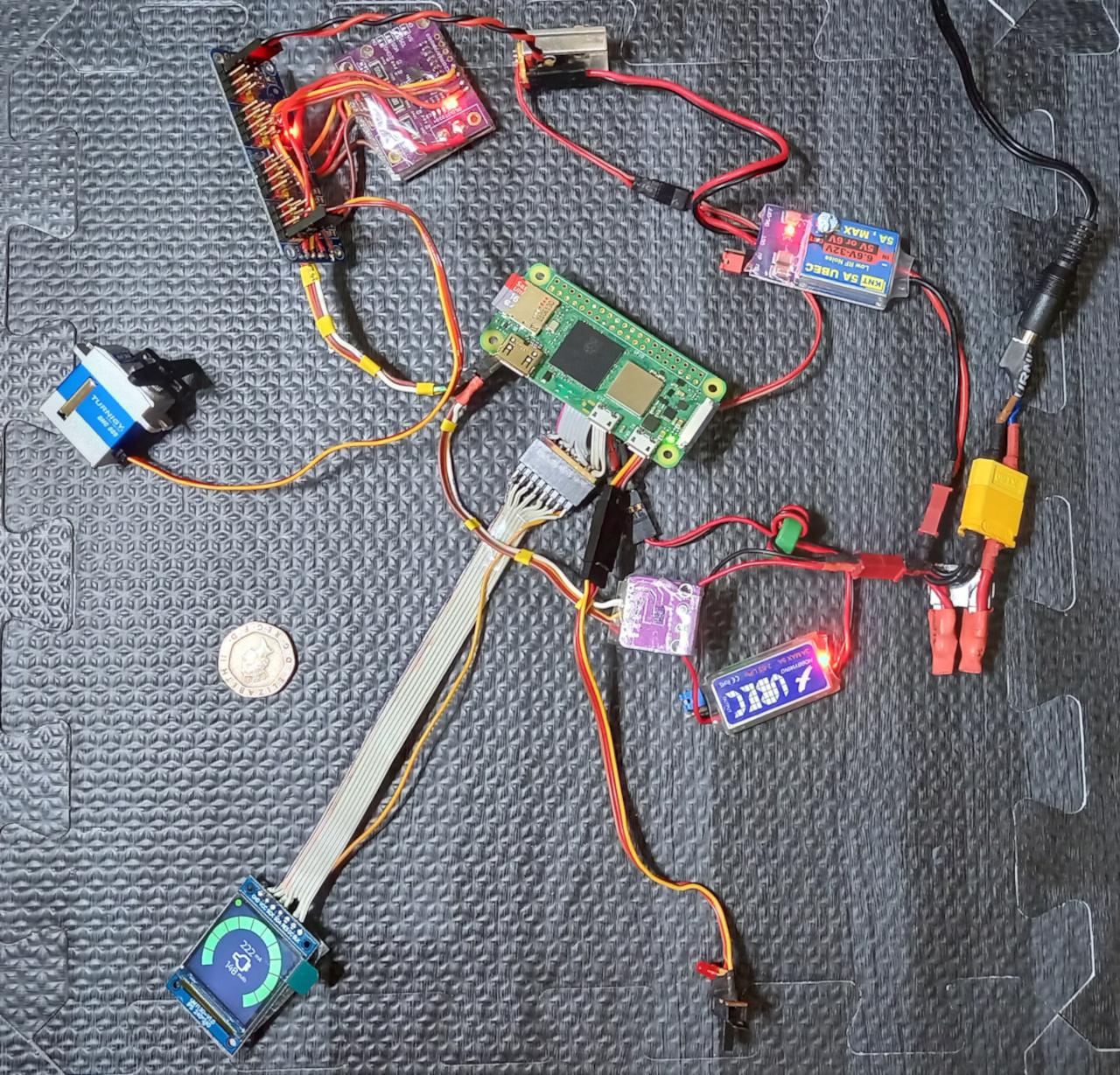
Flig has two BEC (Battery Eliminator Circuits) from RC world - both having ability to use 2S Lipo battery (two 3.7V cells connected serially) to convert 7.4V (8.4V when fully charged) to 5V for driving electronics and PiZero2W and 5V or 6V for driving servos. There are two in order to protect PiZero2W from potential voltage fluctuations when servos are working.
Next is a must for Lipo driven batteries - car fuse immediately after the battery - so in case of short circuit somewhere we do not short the battery (which could make it overheat, catch fire and even explode!).
Since we will be working with a computer (Raspberry Pi Zero) it'll need to be properly shut down, so our electronics needs small way of conveying fact that we would like to disconnect battery to PiZero2W and that's done in exactly the same way as in original 2017 Rover - with a small switch and LED for the feedback. Switch moved to 'on' position for more than 5 seconds would signal to PiZero2W that it needs to shut down while LED will blink during those 5s. If switch is moved back to the original position before - nothing would happen. Except, now we have moving parts (read: servos) moving switch to 'on' would immediately stop operating servos and make them 'limp'. So, which toggle on/off would make Flig stop doing something (probably not doing it right in the first place).
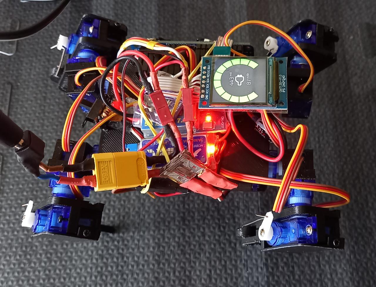
And last, but not least is small 1.5" screen for feedback of state of the battery since now we can measure both voltage and current on both servos and electronics.
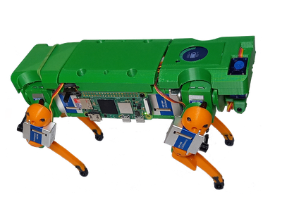
Now all put together we finally have complete robot:
Comments
Comments powered by Disqus