Now target is set - let's get making!
Ideally, we would use small brushless motors with proper absolute positioning senors as direct drives or geared for driving joints, but such miniaturisation is way beyond our capabilities. There was some thoughts of making small harmonic drives or distribute gears along the legs, but current 3D printing is still not at that technological level.
Since PiWars robot need to fit certain dimensions and going really big is going to cause an issue in relatively small PiWars arena(s) (normally around 1500mm x 1500mm), it was easy decision to stick with servos and see to use servos as direct drives of joints (where possible and makes sense).
Hardware
To start we need to define robot axes:
- X axis is going from robot's tail to robot's nose
- Y axis is going from one side to another - from left to right
- Z axis is going from robot's body towards the ground
A leg is to have three servos:
- one to move lower part of the leg - 'the shin'
- one to move upper part - 'the thigh' (direct drive)
- and last to move whole leg 'sideways' - 'the shoulder' (direct drive)
Shoulder servo is going to be fixed to the 'chassis' and will rotate 'the shoulder's' servo perpendicular to the robot's body - along Y axis. Shoulder's servo, along the thigh servo is going to move leg along the X axis - front and back.
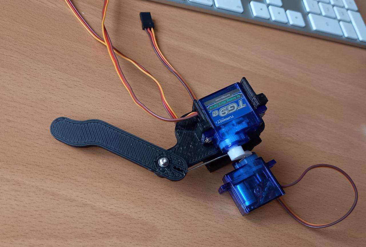
As the aim is to have as much mass of the leg concentrated at the 'hip' along the axis of the shoulder servo, I've decided to move servo that would drive knee higher up and flat against 'shin'. This can be looked as innovation over many (miniature) servo based robots which are described on the Internet that usually have all their servos at joints as direct drive.
Because of size (and, as shown in previous post, having excess of 9g servos) we went with what is normally called a micro servo - HX900 alike 9g servos or servos which are normally 22mm wide and 12mm deep (their height vary).
Here is what leg is like:

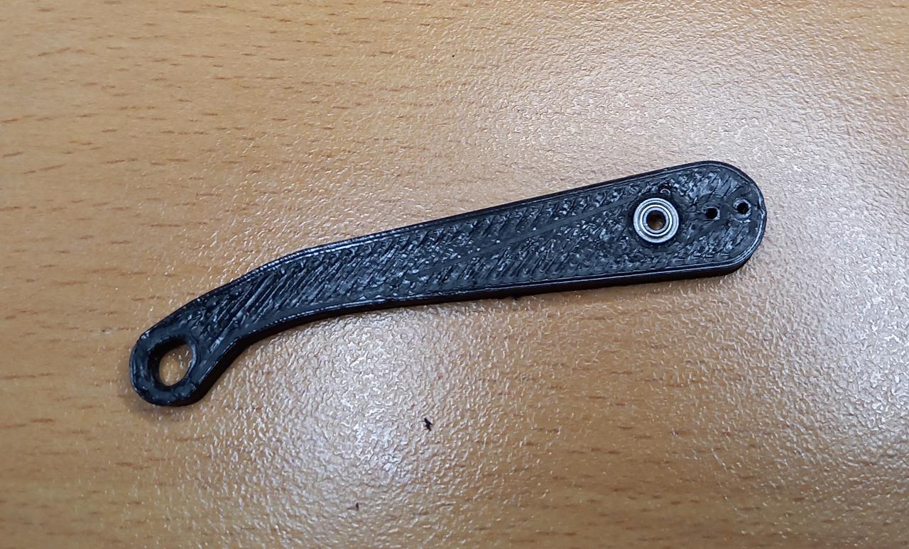
As shoulder and thigh are directly driven by servos, we need only one miniature ball-bearing at the knee. Luckily, I had a couple of all 450 sized clone helicopters rotor heads (old kind with flybars) and they came not only with the appropriate ball-bearings but longer screws, too:

First Software
To move leg there's need for some maths to be done - for inverse kinematics. Fortunately this is one of the simplest case where there are only two angles to be calculated: thigh angle and shin's angle. First we need how long leg needs to be (let's call that 'z') and where we want let to be in relative position to thigh's servo (let's call it 'x' and 'x' is 0 straight below thigh's servo). 'leg_length' is (when shoulder is at 0º) same as 'z'.
Knowing length of shin and thigh we need to calculate where two circles are and where they intersect and where lower (shin one) intersect ground.
l3 = math.sqrt(x * x + leg_length * leg_length) if x != 0 else leg_length

alpha_prim = math.acos(t) if l3 <= l1 + l2 and t >= 0 else 0.0
alpha_second = math.atan2(x, leg_length)
thigh_angle = alpha_prim - alpha_second

x1 = -l1 * math.sin(thigh_angle)
y1 = l1 * math.cos(thigh_angle)

beta_prim = math.atan2(x - x1, leg_length - y1)
shin_angle = beta_prim + thigh_angle - math.pi / 2.0
Shoulder's maths is simple: amount of mm we want to move it to 'outside' (let's call it 'y') and 'height' (which we can call 'z'):
shoulder_angle = math.atan2(y, z)
Here it is how it looks in simulation:

The above would be right leg as 'forward' is positive X axis and on screen that's going from left to right.
All together
And here it is how it looks with real hardware:
 F. L. I. G.
Comments
Comments powered by Disqus